|  Introduction Introduction
The
audio amplifier described in this page uses the LM3875TF
chip by National, the driving
force behind one of the most famous "Do It Yourself" projects
of the last years. It's interesting an interesting device capable
of good sound and the advantage to employ a very small number small
number of external components,which makes it easy to be constructed.
In short... a classic GainClone!
This time dressed in a fancy way, at least for this kind of device,
but with some original and unusual technical solutions.
For more specific information on GainClone, a web research is all
you have to do. You'll find out discussions, schemes, variations,
tweaking and much more. For a quick revision of "what is it",
you may want to refer to the specific
page on Richard Murdy's site,
one of the first to discuss this particular project.
Many others have written on it, in an even broader and more detailed
way. For instance, Nick Whetstone, in his famous
site "Decibel
Dungeon", has an entire section called "GainClone
Pages", which deals with all of its aspects. In a minimal
or "inverted" version, with or without Pre, with regulated
power supplies or not.
Not to be missed.
 Compared
to the standard configuration, I added a few small variations. In
this case, the power supply tension is of +/- 35 Volt, higher of
some ten volt for branch than the one used by Richard. This allows
the chip to supply more power. A little more than 50 Watt per channel
on 8 ohm, for less than the 0,1% of distortion. Compared
to the standard configuration, I added a few small variations. In
this case, the power supply tension is of +/- 35 Volt, higher of
some ten volt for branch than the one used by Richard. This allows
the chip to supply more power. A little more than 50 Watt per channel
on 8 ohm, for less than the 0,1% of distortion.
(For details about the tension/power relations, look through the
datasheet) The electrolytic capacitors
used as filter are Panasonic FC of 2200µF/50V (two per channel)
and the input capacitors is made of Polypropylene of 2,2µF.
The potentiometer, indicated as R1, can be set in the range of values
going from 20 to 50 Kohm. Richard uses a 12 positions Stepped attenuator
of of 35k, I use an Alps Blue of 20k log. This is not a problem.
The main difference is in the way the potentiometer attenuates the
signal.
At the same sound level it may occur that the 20k, set at 12 o'
clock, gives a sound of an intensity similar to the one of 35K,
set at "1" o' clock. Some people prefer a high range of
control in the part in which the sound is low (high attenuation),
others the opposite.
 As
a general rule, it's always preferable to have an attenuator of
less value than the input impedance. In the case of the scheme reported
above, the impedance value is more or less the one of the R2 resistance.
That's to say 22Kohm. The ideal thing would be to use attenuators
of 20K or less. As
a general rule, it's always preferable to have an attenuator of
less value than the input impedance. In the case of the scheme reported
above, the impedance value is more or less the one of the R2 resistance.
That's to say 22Kohm. The ideal thing would be to use attenuators
of 20K or less.
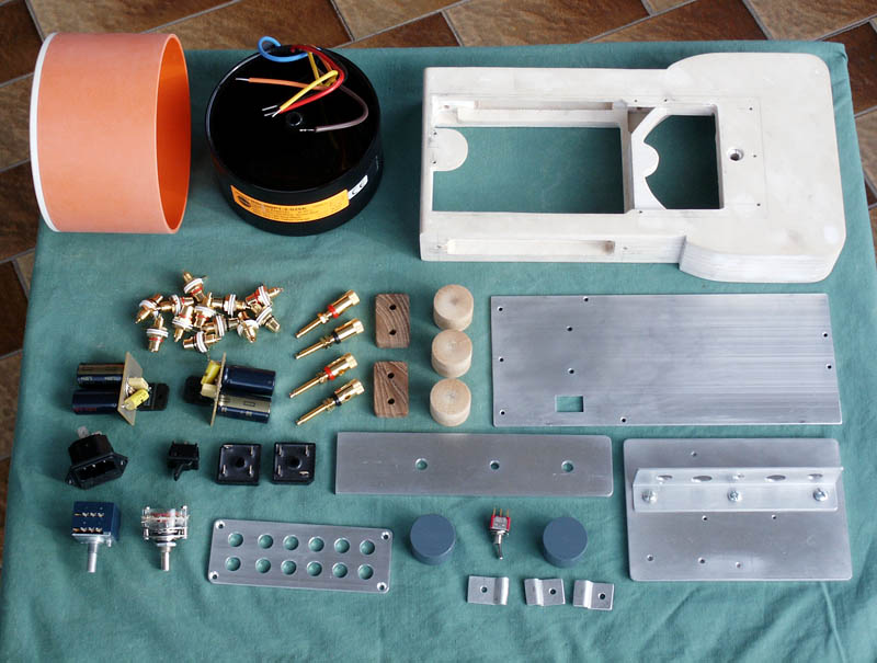
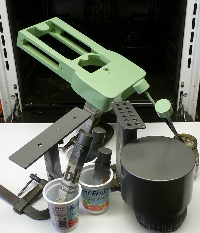
The transformer employed is a Toroidal encapsulated Talema, of 300VA-2x25Volt,
visible in the group photo. The straightening up diodes consist
of two Fagor bridges of 25A-500V. The group is completed by a six
poles/double sector switches, by Palazzo,
(employed as an input switch) a toggle switch for the "ON/OFF"
commutation,another double sector used as "MUTE", a small
IEC panel mounth with integrated fuse and Input/Output connectors.
Finally, scattered on the floormounting, you'll find all the elements
that make up the device.
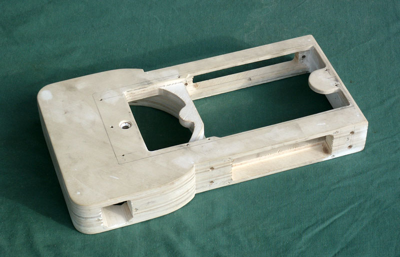
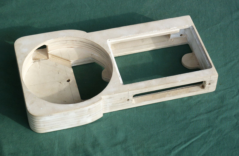
 Here
on the side, you can see the already polished detail of the self-supporting
central body, seen from opposite angles. Here
on the side, you can see the already polished detail of the self-supporting
central body, seen from opposite angles.
They consist in some layers of wood overlapped and pasted to each
other. Multi-layered in two depths: 6 and 10 cm thick. It's not
the quickest way, it needs precision and clear ideas on how to place
all elements, but it allows you to build up even complex models
without too many difficulties. Once the layers have all been glued,
you may start to rough out and polish. A couple of coats of filling
paste, will partially cover the wood texture, which, though it may
look thin and well polished, if not covered, may end to be noticeable
even under the paint. For faultless models, I suggest to give first
a coat of "base"
(a pretty thick paint, usually white or grey, which dries up quickly),
rub it and then give the final colour.
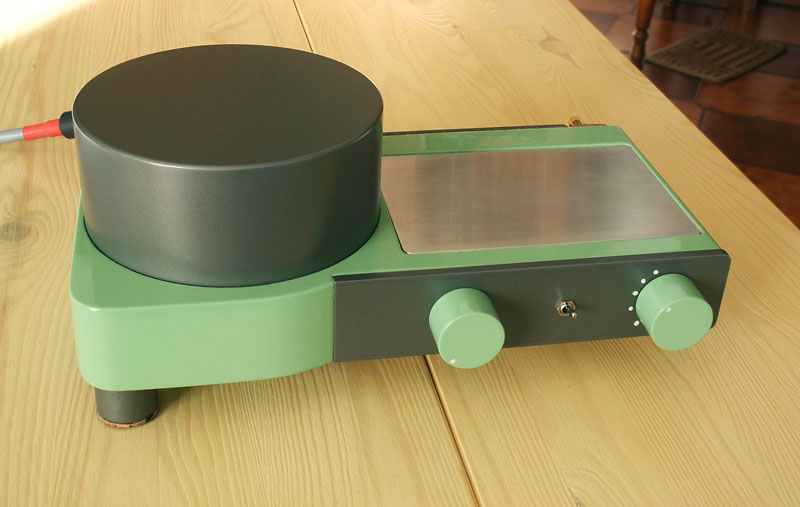
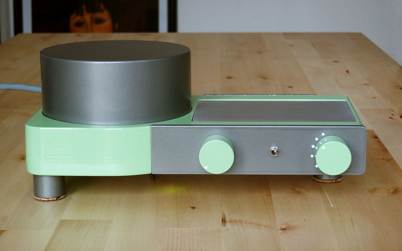
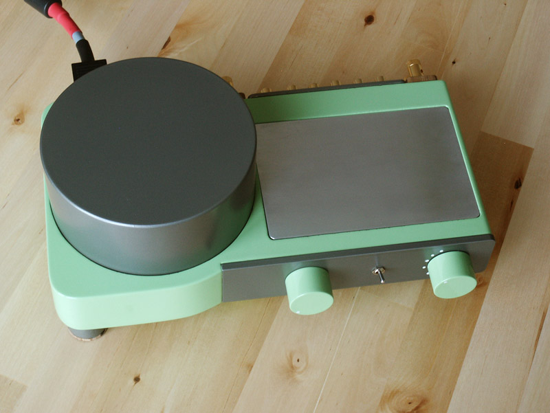
In this case it's a delicious milk-mint (emerald green), set against
the dark-silver grey used for panels, for tootsies and the shielded
covering of the transformer, obtained with a close pipe of pvc,
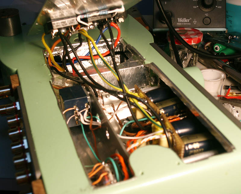
its inner side coated with an aluminium adhesive tape.
The same tape, with infinite patience, has also been used to completely
shield the body. You can see it in that ugly and blurred picture
of the inside (sorry for that!).
I'm not crazy for the box style, but I'm aware that it might be
difficult to imagine a different covering.
 As a matter of fact, if even the main producers actually provide
the same old hat since many years (talking of aesthetics...), I'm
not surprised at the fact that many DIY fans can't think of anything
different.
As a matter of fact, if even the main producers actually provide
the same old hat since many years (talking of aesthetics...), I'm
not surprised at the fact that many DIY fans can't think of anything
different.
As for me, I usually start placing the main components. This grants
me to decide the approximate size
of the object, which are the best points to place the tootsies (if
possible, always three) or which are the best indicated
paths for the signal and power supply cables (the aim is to get
them to be as short as possible and rationally separated
from each other). Only then, I start and imagine the external shape.
Once the model is designed, it's like assembling it is easier to
assemble.
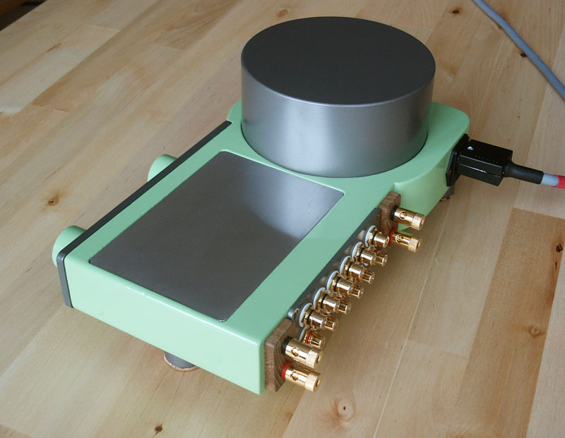
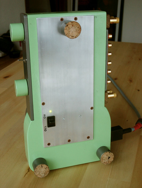
 The
three tootsies are placed as a triangle with the heavy toroidal
in the centre. This solution makes the amp stable like granite.
The "on" switch is placed on the bottom panel, a green
led, not far, lightens the floor under the amplifier. The aluminium
element in the upper side is meant to dissipate both channels and
measures more or less 150x100x5 mm. The
three tootsies are placed as a triangle with the heavy toroidal
in the centre. This solution makes the amp stable like granite.
The "on" switch is placed on the bottom panel, a green
led, not far, lightens the floor under the amplifier. The aluminium
element in the upper side is meant to dissipate both channels and
measures more or less 150x100x5 mm.
I tried the amplifier at a cracking volume for at least a couple
of hours, without the heatsink ever overheating. It's hot, but it
hardly gets to temperatures higher than 40-45°C. Maybe during
the summer, with 30 degree in the shadow, it will prove good to
make toasts (I hope not so!:-)
I will keep myself informed, now it is no longer mine.
It is a gift, I hope it may bring a lot of satisfaction!...:-)
Conclusions.
Some short remarks.
The GainClone is a very good amplifier. Valuable components, a compact
layout and a correct managing of the masses, together with a good
power supplying, are the key to getting high performances. The simplicity
of the circuit allows to lodge it in a small-sized cabinet.
If you have a little time, patience and a certain manual skill,
you can move further, designing a new one, or inserting its parts
in a pre-existing case, fit for the purpose. (But always keeping
in mind and considering all the issues connected to safety and electricity
use).
For instance, never thought of the rectangular backed clay vases?
Yes!, those used for plants! You can find them easily in a variety
of shapes and colours. Backed clay, as ceramic, it's a very compact
material, has a good insulating power and is partially a thermoconductor.
If you also find, who sells China vases for Bonsai.. I'll say no
more!;-)
-
Marco Saccani, january 2006 - www.moxied.com
|